CASE STUDY
Air con electric box part
Due to our variety of machinery at Constant we undertake a large amount of part and component manufacturing, including shop fitting brackets, drain trays and electrical box parts for customers such as brewery chains, supermarkets and air conditioning manufacturers.
This ‘How it’s Made’ is a little different, giving an overview of how we go through the design, sampling and manufacturing process using various form tools, hinged component design, machine and fast bends for an internal electrical box for an air conditioning unit.
Our existing client approached us to redesign an electrical box for the internal electrics of a large industrial air conditioning unit.
The part is composed of a hinged enclosure/lid and a main body unit. In the first instance, our customer emailed their original specification and drawings in PDF and CAD file forms.
Services
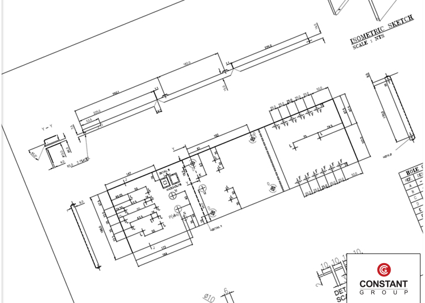
CAD design
Our CAD engineer took the customer’s drawings, and programmed them to work effectively on our suite of machines. This job was programmed in Radan.
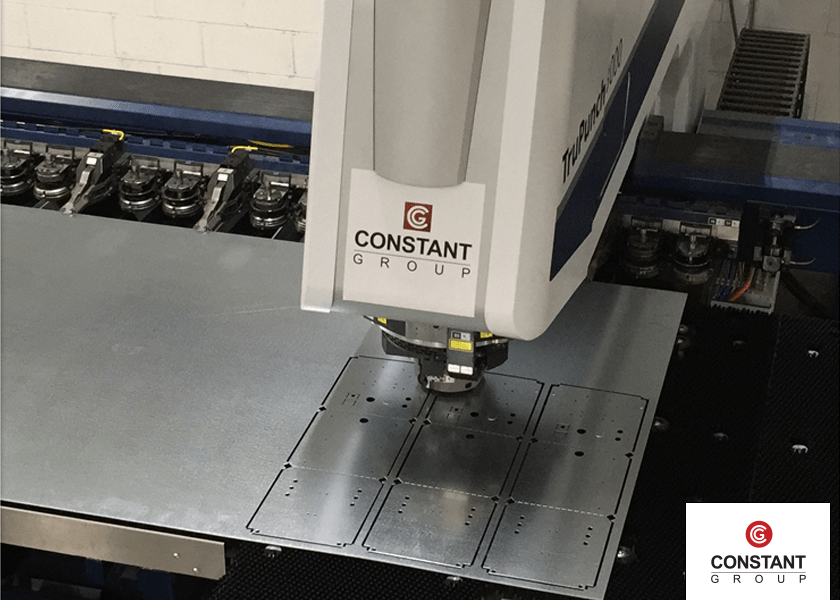
CNC punching
The samples were then sent to the CNC punch machine to be cut on a sheet of galvanised steel, 0.9mm thick. When we produce a sample such as this, we typically make three. One for the customer, one for the CAD team for reference and one spare.
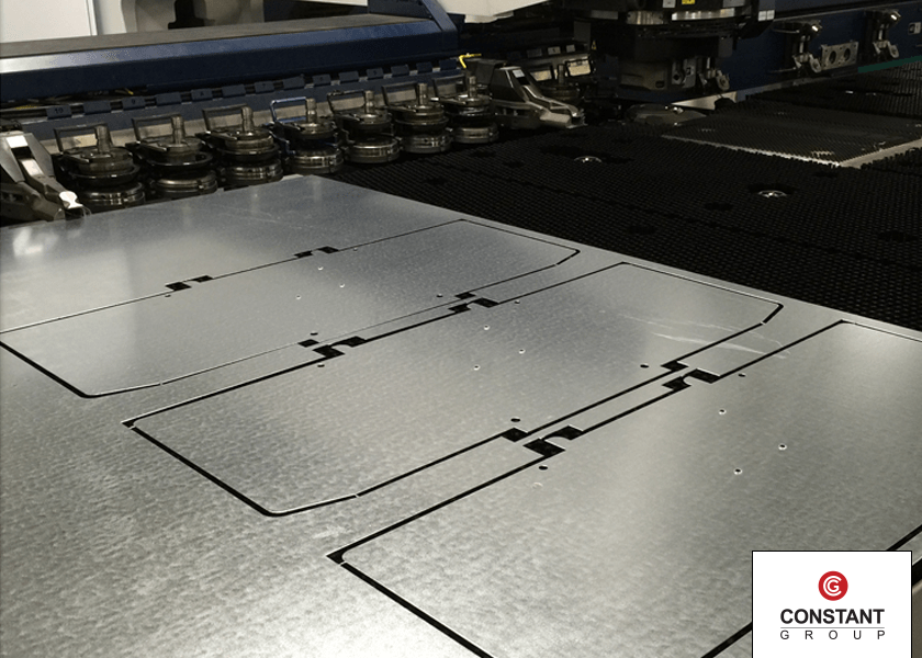
Cutting
Next on the CNC punch machine was the main electric box. The sheet of metal from stage 3 is rotated, and the punch machine selects the next program. It first goes through cutting a range of wiring holes, then starts to move around the sheet metal cutting the various forms and sections out. This particular job is quite complex with over 16 tool changes, including a few specialist shapes and forming procedures.
The vibrations seen in the video highlight the force of the TruPunch machine cutting out the larger holes and when it slices down the metal to form the edges of the box.
Did you know?
The punch machine may sound quiet violent but this extremely technical machine is floating on effectively an air bed to reduce factory noise.
Forms
Due to our extensive range of tools for our punch machines, we’re able to produce these types of complex components. This particular part involved this range of tools:
- Circular punches; 5mm through to 20mm diameters
- Up form dimple 16x16mm
- Square 15x15mm
- Camlock 10x8mm
- Electrical knockout 20mm diameter
- Rectangles from 6x2mm to 76x5mm
- Corner radius 5mm
Bending
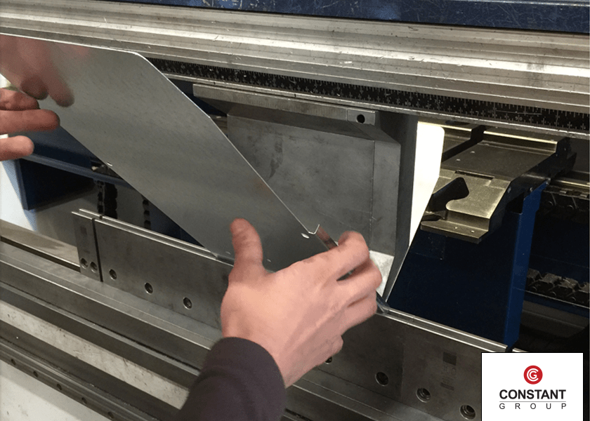
There is no welding involved in this job, but a vast amount of tight, and expertly programmed, bends. Firstly one of our experienced Press Brake Operators programmes the machine telling it all the vital information such as bend positions, order, length of bends and tools to be used.
The team set up the dies and punches, and gets to work bending the pieces of metal, checking everything is aligned at each step. However, there are several bends in this part that aren’t ‘machine’ bent, more on that later!
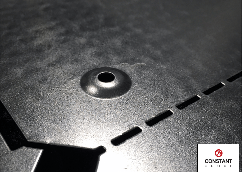
Fast bends
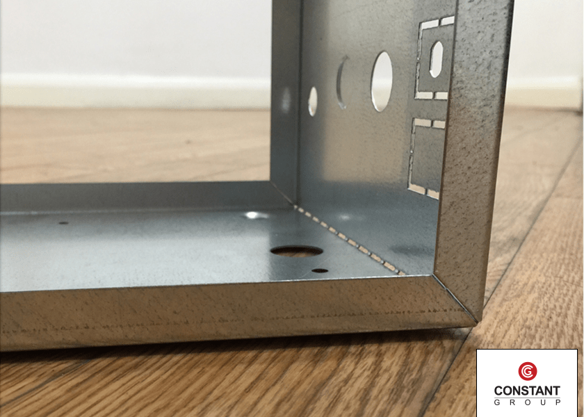
The client wanted to be able to insert their wires, external components such as capacitors and switches, and fix it to the exterior unit before the final bends were formed. As a result the part was designed with ‘fast bends’ down those edges.
The fast bends look like large perforation marks and are quite simple to bend with a small bit of force from the assembly operator’s hands. The best bit, it saves minutes on the wiring line at the customer’s site because they have better access.
Final product
Once the samples were produced we sent them to the customer for review and approval. The customer determined they required three more electrical wiring holes, and a few more fixing bracket options, so the specification was adjusted accordingly and our CAD team updated the, drawings, revision change register and programs before we commenced mass production.