Due to our versatile manufacturing site, and diverse range of machines and skills on the shop floor, our existing customers often approach us to manufacture new parts for them alongside their regular stock orders. This month we followed one such project, a camera arm with fixing bracket through the factory floor.
This camera bracket involved a few unique elements from steel tube fast bends through to HR4 (Hot Rolled Steel) versus the usual CR4 (Cold Rolled Steel).
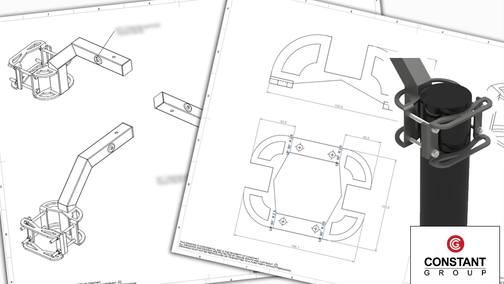
Our client approached us with an old bracket design, and asked us to redesign it and make it more modern and compatible with a wider variety of poles and fixtures it may be applied to. Once the concept was down on paper, our CAD engineer plotted it out in Solid Works, and produced a 3D render for client approval.
The design involves a special fast bend, which was designed and tested before approaching the customer with the overall design. The reason for this fast bend is to speed up production by reducing welding and linishing time.
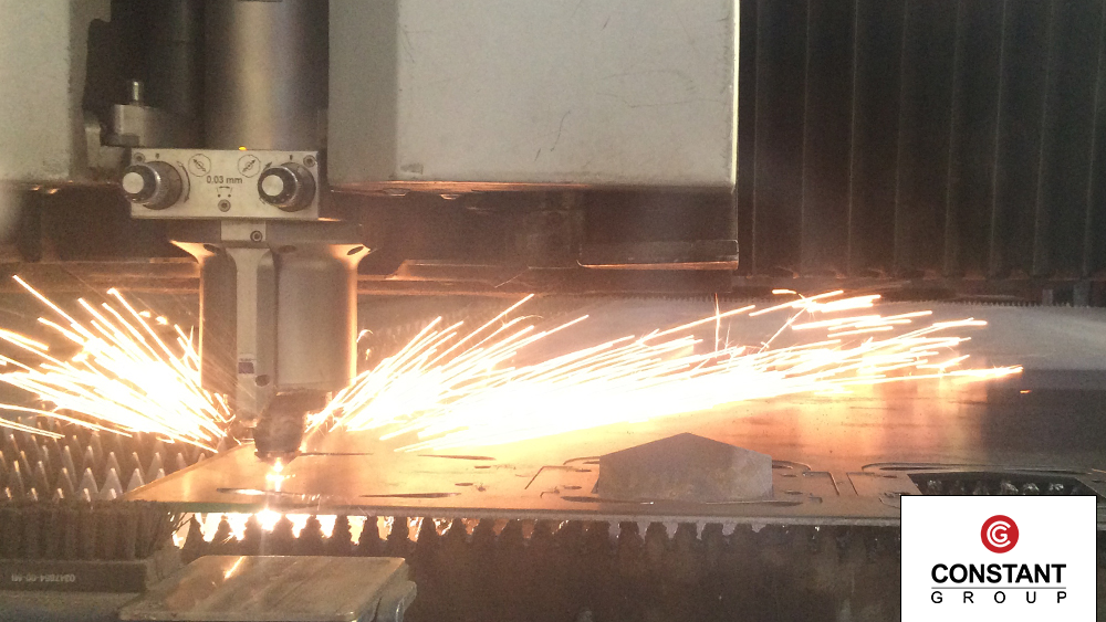
Laser cut
The bracket involved sheet metal and box section. First the sheet metal was cut on our laser cutting machine, out of hot rolled steel as well as cold rolled steel. Due to the durability and application of the camera bracket, some parts were made from thicker steel, HR4.
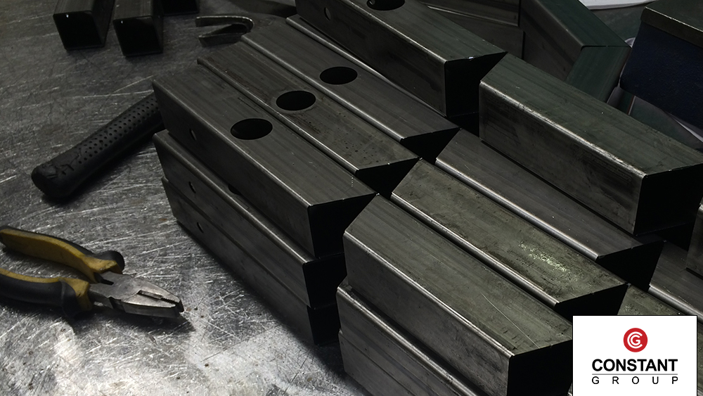
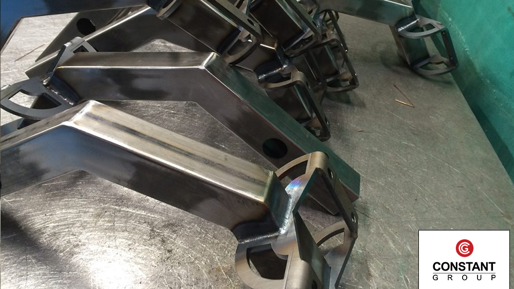
The box section that was tested in step one is cut in mass, with lengths being cut, then v shape fast bends cut out to allow for the fast bend process.
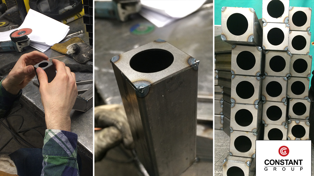
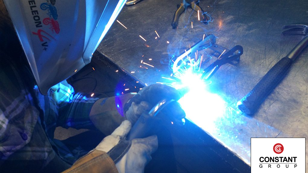
Welding
Once the box section was cut, the welder bends the box section, and holds it in place with a jig. He then tack welds the bends to keep them in place.
The welder now pops the end stop on and tack welds that in place, finishing the tack welding of the box section arm of the camera bracket.
TIG welding the box section
Now the box section has all it’s parts and bends tack welded into place, the welder systematically goes around all the tack welded edges and TIG welds them.
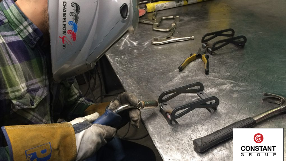
Welding
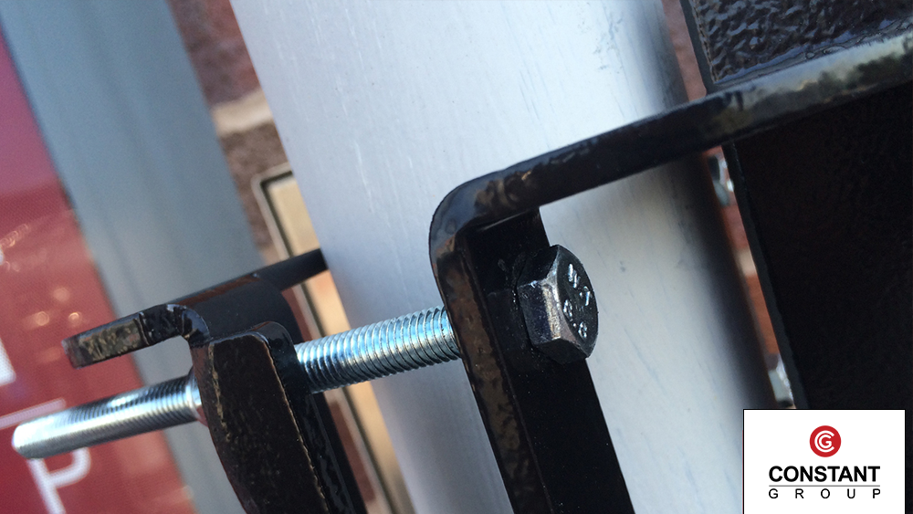
The box section arm has an adjustable fixing bracket attached to the end. This fixing bracket allows for the camera arm to be fitted to any shape pole such as a lamppost for CCTV cameras.
Once the metal pieces were cut on the laser cutter, the welder started to construct them together, tack weld them in place and then TIG weld along the joints.
Once the fixing bracket has been welded together, like the box section arm, the bracket is grinded down to give it a smooth finish for powder coating.
Now both the box section and the fixing bracket are welded and finished, one half of the bracket is welded to the arm to form the main body.
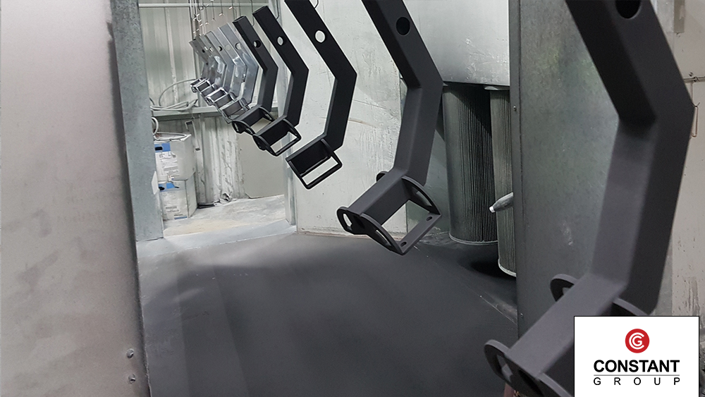
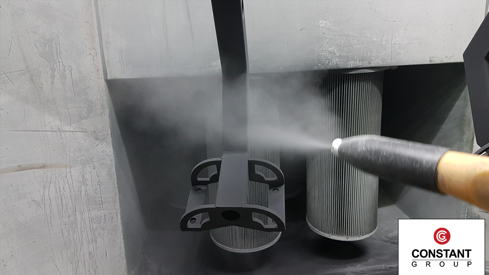
Powder coat
The camera arm body and final fixing bracket, are sent to the powder coating department.
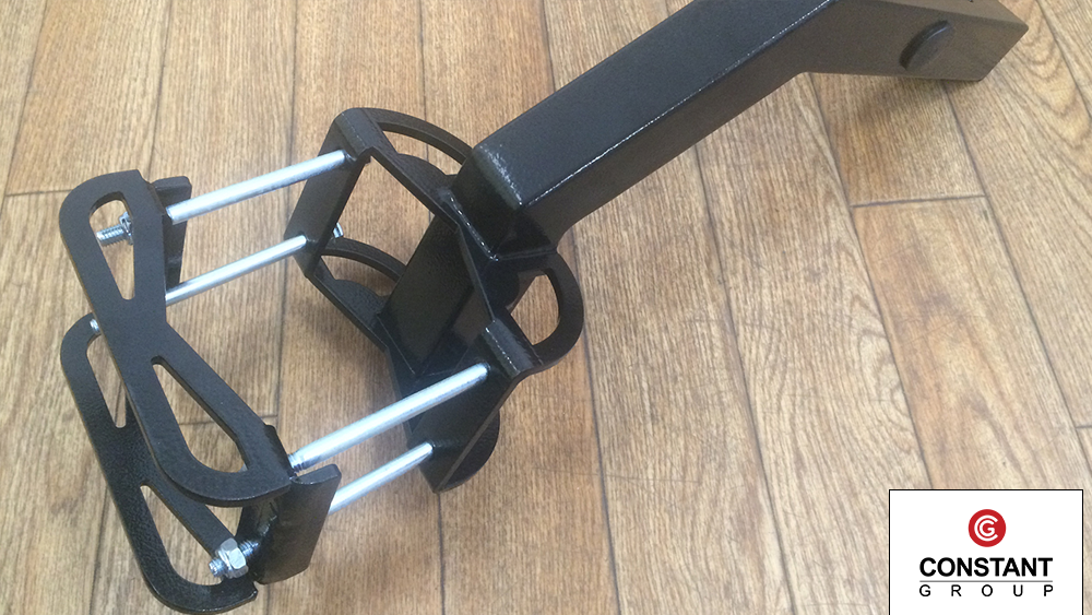
Assembly and tested
Once cooled, the camera arms were quality tested, and then packed up for the customer. We managed to take a few photos before the last one was wrapped and packed.
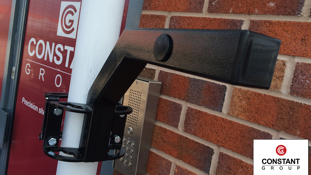
Final product
We popped it on our reception canopy poles to demonstrate the fixing bracket. The bolts and design were as such so it can be applied to a large range of poles and structures to make it as versatile as possible.
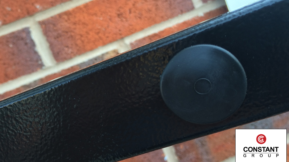
The arm incorporates holes, which we seal up with rubber glands. The holes allow for the client to fix their camera or electronic devices onto the arm, and thread cables through the hollow box section. There are holes in various places including the side of the arm and the bottom of the arm.